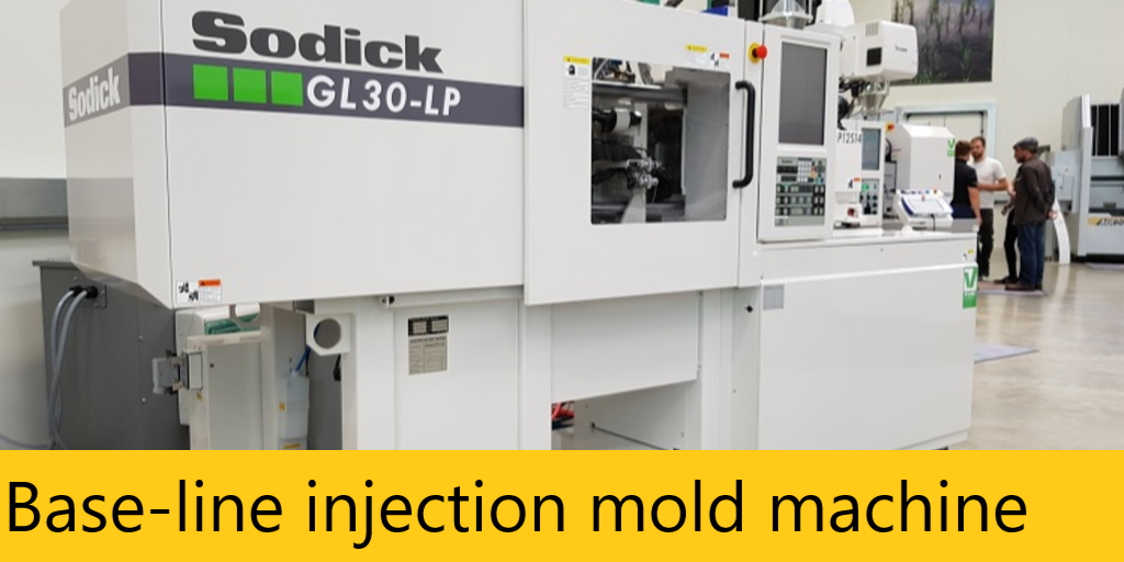
Base-line injection mold machine
Several Factors Could Be the Issue
Base-line injection mold machine – Maverick Systems technicians are all factory trained and certified by Hamar Laser for Injection Molding Machines. All have hands on experience working with customers to provide them with alignment solutions on their injection molding machines. We have run into various obstacles along the way with foundation settling issues, level issues, platens not parallel to one another, molds not parallel to the platens, bent tie rods, injectors not aligning with molds and the list goes on.
Base-line your Injection Molding Machine
We recommend base lining your machine. While there may be only one issue with the machine there may also be several factors creating that problem. If you initially find the platens are not parallel to one another, stop there and try to find out why. Base lining the machine and doing a full inspection of level, flatness, squareness and parallelism of all the components may help you in your search.
When sufficient evidence is gathered, you should then correct all the issues to prevent similar mistakes in the future. On the bigger injection molding machines (1500 ton+), a series of data collecting needs to take place that requires more than one set up. Though it may require a full day to troubleshoot, afterward you will know the full geometries of the machine and where to start with corrections.
Read More : Mavericksystemscorp.com
Reduce Downtime Changing Molds
Changing a mold is time consuming and realignment is a necessity. If a mold is slightly out of parallel to the platen, costly flashing and premature wear can occur. Inadequate alignment also results in excess wear on the injection-molding machine and can even lead to tie-bar breakage. With each tie bar costing at least $10,000, proper alignment is crucial. Maverick Systems can save you time and money with the mold changing process. Rather than using the traditional methods of alignment, we can “buck-in” to your platen plane and provide live alignment data. Misalignment errors can then be quickly adjusted using just one setup. Use of the Hamar laser L-723 speeds the alignment process significantly, and also reduces tooling and maintenance costs.
Reduce Stack Up Errors
One of the biggest complications with aligning machine tools using conventional methods is that many different alignment tools must be used, requiring a lot of time and increasing stack-up errors. Another concern is that an alignment is only as good as the tools used to perform it. The machinist master level is a good example: it has a resolution of .0005″ per foot, not very accurate for today’s ever-tightening tolerances.
The L-723 laser planes, by contrast, are flat to 1/2 an arc second (0.00003″/ft or 0.0025mm/M) in a 180° sweep and 1/4 arc second (0.000015″/ft or 0.001 mm/M) in 90° sweep. The laser planes are square to each other to within 1 arc second (0.00006″/ft or 0.005 mm/M). They further have the advantage of creating a single reference from which to measure machine geometry, significantly reducing stack-up errors.