Extruder barrel alignment
The facts about Extruder Barrel Alignment or Bore Scoping
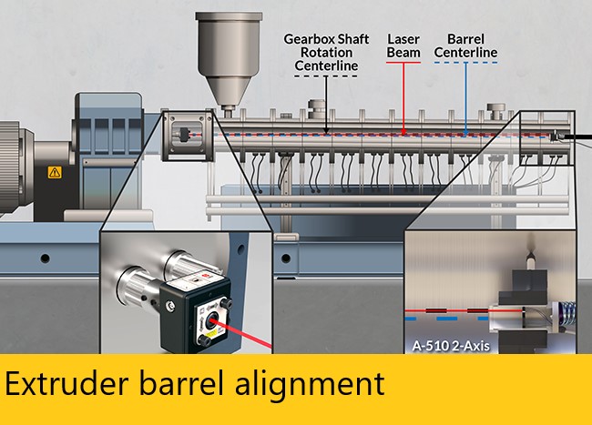
Extruder barrel alignment – Most extruding machines are built with the thrust bearings, shaft assembly, and the output shaft of the gearbox as one unit. The thrust shaft (which is splined, or keyed) holds and turns the screw, which is the centerline of the axis of rotation. If any of the components are not aligned from the centerline of the thrust shaft there will be friction between the barrel and screw or feed chamber and screw. Sometimes, both situations happen, depending on the amount of error off centerline. If there is friction between the barrel and screw, the amount of wear will increase causing either the barrel or screw (or both) to wear faster increasing your replacement costs dramatically.
The feed chamber is the next component. If the feed chamber screw guides are offset too far from the thrust shaft centerline, (feed chamber offsets are discussed in more detail in the offset section) it will put strain on the gearbox thrust shaft bearings, causing them to wear faster.
Next is the barrel input. Again, it’s important to know if there is an offset from the thrust shaft centerline either horizontally or vertically; it could cause the screw to rub at the input end of the barrel. More importantly, the offsets of the feed chamber need to be the same as the offsets at the barrel input. Offsets that differ would definitely create friction between the screw and the input end of the barrel. If offsets sound confusing, you can read more about them in the offset article.
Last is the barrel output. Most errors will be found from the centerline of the thrust shaft, and will usually be in both vertical and horizontal. Excess misalignment here will cause friction between the screw and barrel somewhere in the length of the barrel. Sag can also be an alignment issue in longer barrels.
Read More : Mavericksystemscorp.com
Taking all of this into consideration, the following paragraph should make it more clear as to why the extruder components should be aligned to the centerline of the axis of rotation and why the thrust shaft is the logical choice for establishing the centerline.
Tolerances between the barrel and screw will average .008 total clearance, which is only .004 on all sides. The extruder is designed to shear, melt, and mix the plastic materials to give a good, uniform flow. If the output end of the barrel is out of alignment, then the screw is rubbing against the barrel at some point. At that contact point, there is minimal shearing and minimal mixing because there is no clearance at the rubbing point. However, there is a hot spot generated from frictional heat due to the screw rubbing against the barrel, causing the plastic material to melt hotter and faster. Now you have an area of material that is of different consistency. On the opposite side of the screw, there is also an area of material that is of different consistency. Because you have a wide gap of .008 that the plastic material is rolling over, not shearing, or mixing properly, the plastic material here will be cooler and harder. Now that you have plastic materials flowing at an uneven temperature, pulsating and surging has to take place. While it may be a very small amount, it could be serious enough that you can’t hold size.
The thrust shaft is what holds and turns the screw. If you have the feed chamber and the barrel aligned to the centerline of the thrust shaft, it will alleviate the friction areas in the barrel and allow the proper amounts and consistency for a uniform flow.
Maverick Systems can bore scope your extruder barrel using the latest laser technologies available. Giving you the most accurate barrel alignment possible.